Connecting RS-485
GOBLIN 2 includes a circuit designed to communicate with industrial sensors dedicated to important processes in measurements of variables such as corrosion, humidity, temperature, pressure, among others.
In this brief tutorial, we’ll see how to carry out the RS-485 communication with an industrial sensor so it can be fed by its corresponding voltage (24V DC) with GOBLIN 2 from the Arduino IDE.
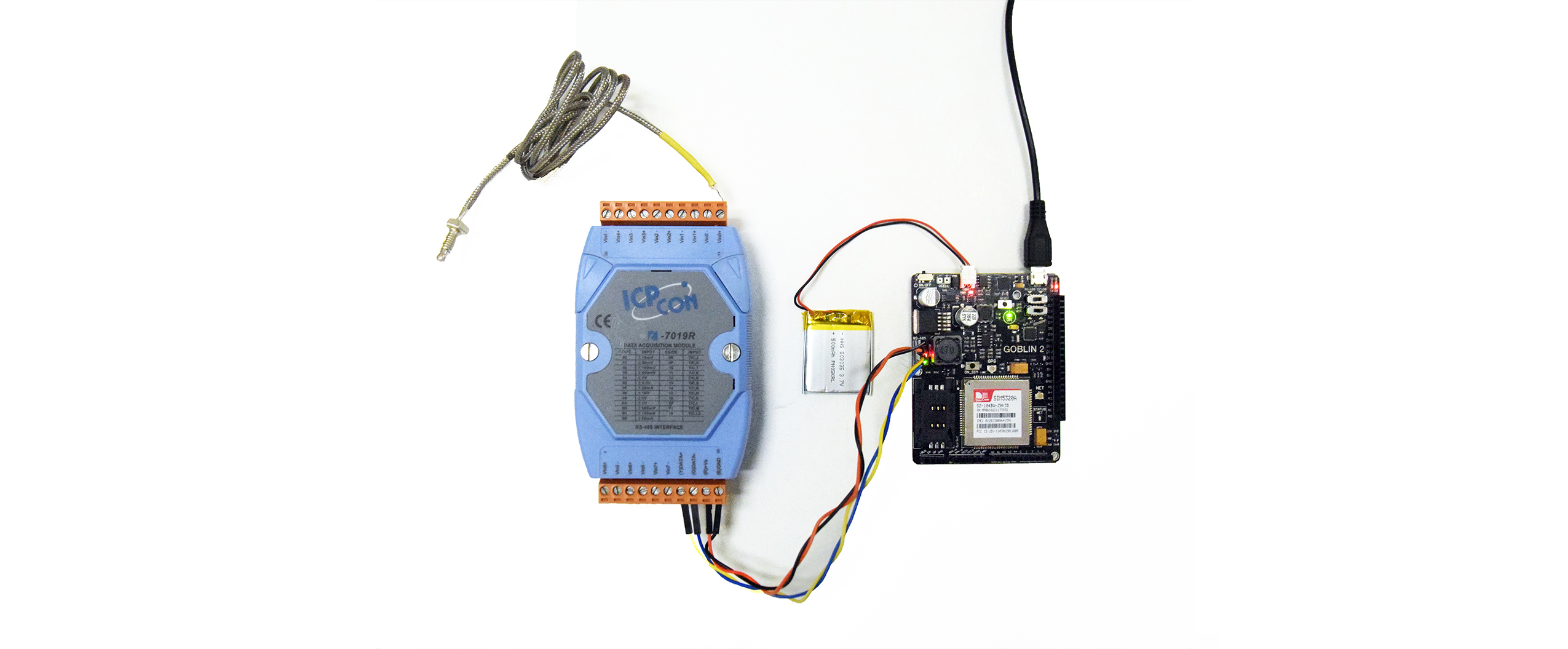
We’ll use an analog input module that measures current (4-20 mA, 0-20 mA), voltage (0-10mV) and thermocouples J, K, T, among others. It is a i-7019R module from the brand “ICPDAS” with a feeding voltage 10 ~ 30V DC, transmission speed 1200 to 115200bps. (For more specifications see the data sheet of the sensor).
This time we’ll use the module to measure temperature with a thermocouple type K connected to channel 0 (Vin0).
1- Connect the i-7019R module to 24Vdc and to the RS-485 protocol, also connecting the battery Li-ion 3.7v to GOBLIN 2.
2- We’ll start by creating a new project on Arduino and name it “COMUNICACION-RS485”, in which we’ll type the next code, getting it from here.
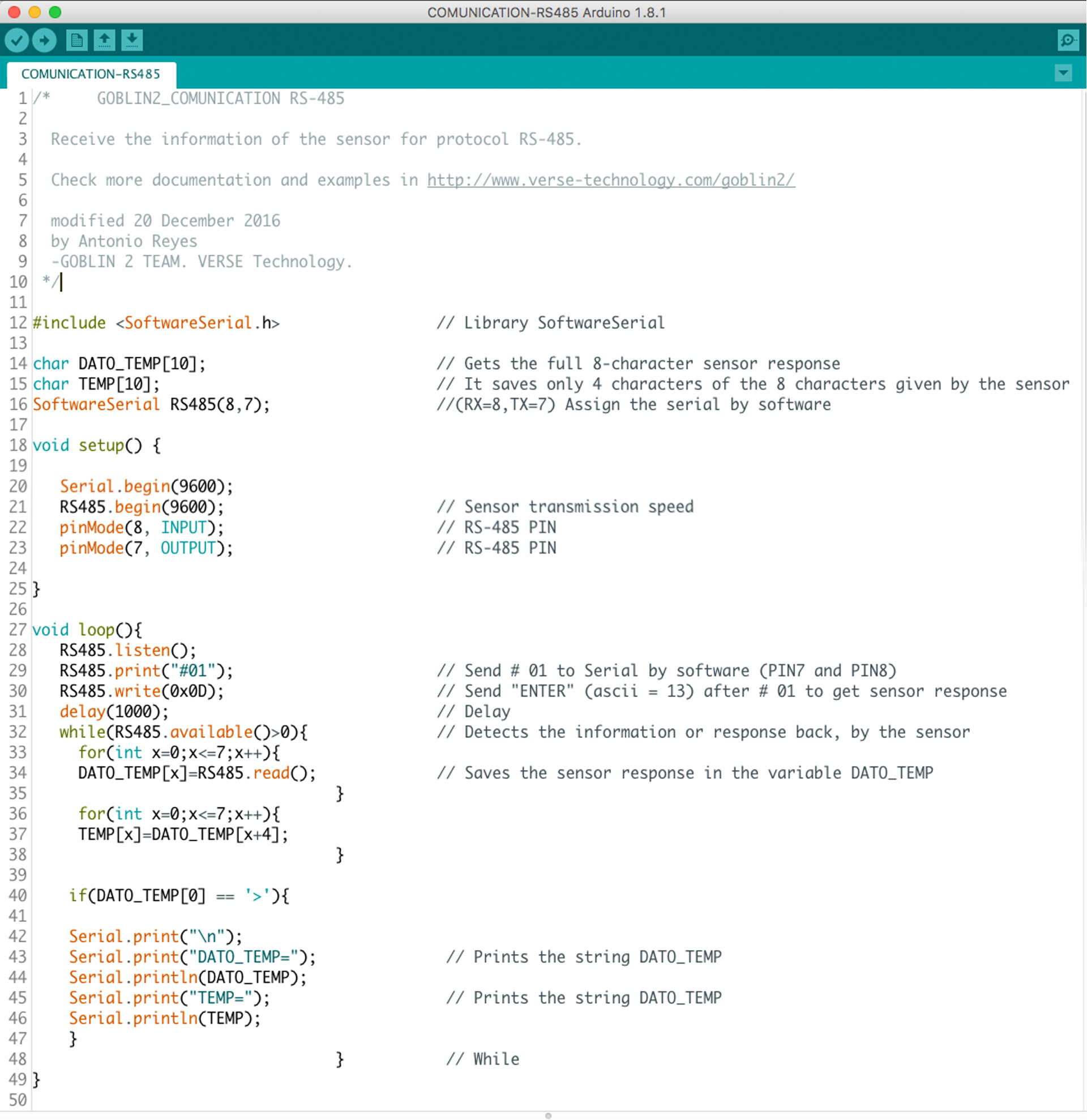
3- For this example, we’ll describe the software part of the declaration of the PINS 7 and 8 of GOBLIN 2 which have communication with the module of the RS-485 protocol.

4- We’ll declare the speed in which the sensor will work, in this case will be 9600 Baudios.

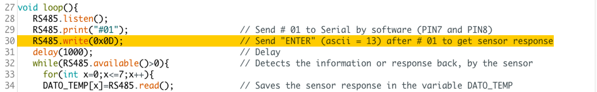
5- In order to know the value of the channel 0 variable (Vin0), you need to send the command (#01) then press ENTER (in ASCII is 13 = 0x0D) to finish the order so we can read the temperature of the thermocouple connected.
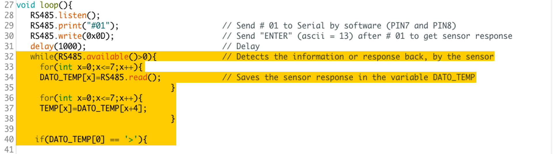
6- The sensor returns the value of the temperature in 8 characters and it’s saved in a string named “DATO_TEMP”, some characters, which are not relevant for us, will be eliminated from the string, leaving the temperature value in 4 characters from other chain named “TEMP”.
7- Once we have the temperature of the sensor saved in the string “TEMP”, it’ll be showed on the serial monitor from the IDE Arduino, after sending the temperature value to GOBLIN 2, an ENTER is also sent but I’ll not be showed on the serial monitor.

8- Observe the communication between GOBLIN 2 and the sensor through the LEDs of the RS-485 module. The red LED indicates that the signal is sent from the GOBLIN 2 to the sensor (#010) and the green LED indicates the answer from the sensor (temperature).
9- Load the program to GOBLIN 2 and open the serial monitor where we’ll observe the string “DATO_ TEMPO” which contains some characters that are not of our interest like (>,+,00), for this case that are only positive temperatures, they ‘ll be eliminated and the string will be as the string “TEMP” where only 4 characters remain.
